Manufacturing & Fabrication Considerations for IC Boards from Design to Assembly
In the intricate world of electronics, nothing quite captures the blend of art and engineering like the Integrated Circuit Board (IC PCB). These aren't just green slabs with copper lines; they are the central nervous system of every electronic device, from the smartphone in your pocket to the supercomputer crunching complex data. But bringing these crucial components to life, from a flicker of an idea to a fully functional board, involves a myriad of nuanced Manufacturing & Fabrication Considerations for IC Boards. It's a journey where meticulous design choices directly impact production realities, making effective collaboration between designers, fabricators, and assemblers not just helpful, but absolutely essential.
At a Glance: Key Takeaways for IC Board Manufacturing
- Design First, Always: Every fabrication and assembly choice begins with a well-thought-out schematic and layout, considering components, power, and signal paths from the outset.
- Material Matters: The right PCB material (e.g., FR4, Rogers) is crucial for performance, especially in high-frequency applications.
- Layering for Complexity: Multi-layer boards are common for complex ICs, requiring precise stack-up and via formation during fabrication.
- Precision in Production: Fabrication relies on highly accurate processes like drilling, etching, and plating to create the microscopic circuits.
- Assembly's Role: Choosing between Surface Mount Technology (SMT) and Through-Hole Technology (THT) impacts component placement efficiency and board density.
- Quality is Non-Negotiable: Rigorous testing, including AOI, X-Ray, and functional tests, is vital to catch defects and ensure reliability.
- DFM is Your Friend: Designing for Manufacturability (DFM) saves time, cost, and headaches by anticipating production challenges early.
- Partnership is Key: Successful IC board production hinges on seamless communication and expertise sharing between all stakeholders.
The Blueprint: Design Phase Considerations for IC Boards
Before a single piece of copper is etched, an IC board begins its life as a concept, meticulously refined through several critical design stages. This isn't just about drawing lines; it's about anticipating the physical challenges of fabrication and assembly.
1. Schematic Design: The Functional Heartbeat
Think of the schematic as the logical roadmap. Here, you're defining what the circuit does and how components interact.
- Component Selection: This is where you choose the specific resistors, capacitors, coils, and, most importantly, the Integrated Circuits (ICs) that will populate your board. Your choices are driven by the application, operating conditions (voltage, current, temperature), cost targets, and required performance levels. An IC or microcontroller usually sits at the core, with its peripheral components strategically placed around it, all guided by detailed datasheets.
- Circuit Connectivity: You're mapping out all signal paths and power connections. This often involves specialized computer-aided software like Eagle, Ki-Cad, or Altium Designer, which helps visualize and organize the electrical connections.
2. PCB Layout Design: Bringing Logic to Life
Once the schematic is solid, it's time to translate that logical design into a physical reality on the board. This phase is rife with fabrication considerations.
- Layer Configuration: How many layers does your board need? Simple designs, like a basic 555 timer circuit, might get by with two layers. However, complex circuits, especially those featuring large ICs like an STM32 microcontroller, almost always necessitate multilayer PCBs. These extra layers provide distinct planes for signals, power supply, and ground, critical for minimizing noise and improving signal integrity.
- Component Placement: This is more than just finding an empty spot. Strategic placement means positioning ICs generally at the center of their functional blocks and placing actively communicating components as close to each other as possible. This minimizes signal travel distance, reduces latency, and helps prevent signal degradation and coupled noise—all critical factors for high-performance boards.
- Trace Routing: The copper pathways (traces) that connect components are sculpted here. You'll follow strict design rules to prevent issues like impedance mismatches, signal reflections, or crosstalk. Careful routing ensures that signals travel cleanly and efficiently. Learn more about IC board design principles, especially regarding trace width, spacing, and impedance control, are paramount at this stage.
3. Simulation and Validation: Proving the Concept Virtually
Before you commit to expensive physical prototypes, simulations help catch issues early.
- Pre-Fabrication Performance Checks: You'll confirm that IC operating voltage, current, and temperature ratings align with their datasheets.
- Signal Integrity Analysis (SIA): Tools like SPICE or Hyper Lynx are used to identify and mitigate potential problems like signal reflections, crosstalk between adjacent traces, or impedance mismatches that could degrade signal quality.
- Design Verification & Rule Checks (DRC): Automated checks ensure all design requirements are met and flag any geometric errors in the layout, such as traces too close together or components overlapping. This step is a critical gatekeeper before fabrication.
Bringing the Blueprint to Life: IC Board Fabrication
Once the design is flawless (on paper, at least!), the physical manufacturing process begins. This is where raw materials are transformed into a functional circuit board.
1. Material Selection: The Board's Foundation
The choice of substrate material profoundly impacts the board's electrical and thermal performance.
- FR4: The workhorse of the industry, FR4 (Flame Retardant 4) is a composite material made of woven fiberglass cloth with an epoxy resin binder, laminated with copper foils. It offers a good balance of electrical, mechanical, and thermal properties for most applications.
- Specialty Materials: For high-frequency circuits (e.g., RF applications), materials like Rogers or Teflon (PTFE) are often preferred. Their superior dielectric constant and thermal coefficient properties minimize signal loss and ensure stable performance at higher frequencies.
2. Creating the Layer Stack-Up and Lamination
This step defines the internal structure of your board.
- Layer Configuration: Based on your design's complexity, signal integrity needs, and power supply requirements, you'll define the number and distribution of signal, power, and ground layers.
- Lamination: Inner layers are fabricated first, forming the core. Then, additional layers of prepreg (epoxy-impregnated fiberglass) and copper foil are added and bonded together with immense heat and pressure, creating a rigid, multi-layered structure.
3. Drilling and Via Formation: Connecting the Layers
For multi-layer boards, electrical connections between layers are made through holes called vias.
- Drilling Precision: Computer Numeric Control (CNC) equipment drills holes with incredible accuracy, often down to 100 microns. For extremely delicate or small vias (microvias), laser drilling is employed.
- Via Types: Vias can be through-hole (connecting all layers), blind (connecting an outer layer to an inner layer), or buried (connecting two inner layers). After drilling, these holes are plated with copper to ensure electrical connectivity.
4. Copper Deposition and Plating: The Conductive Pathways
After drilling, the entire board undergoes an electrolytic copper plating process.
- Enhancing Conductivity: This step uniformly deposits a layer of copper onto the traces, pads, and, crucially, the inside of the vias. This increases their thickness and conductivity, ensuring robust inter-layer connections and reliable current flow.
5. Etching and Patterning: Sculpting the Circuits
This is where the actual circuit patterns are formed from the continuous copper layers.
- Photoresist Application: A light-sensitive material called photoresist is applied to the copper surface.
- UV Exposure: A photomask, which contains the exact circuit pattern, is placed over the photoresist. UV light is then projected through the mask, exposing specific areas of the photoresist.
- Developing and Etching: The exposed photoresist is chemically developed, which either hardens or softens it, depending on the type. The softened photoresist (and the copper underneath) is then chemically removed (etched away), leaving only the desired copper traces and pads.
- Photoresist Removal: Finally, the remaining photoresist is stripped off, revealing the perfectly formed copper circuitry.
6. Solder Mask & Silkscreen Application: Protection and Identification
The final touches for board protection and usability.
- Solder Mask: A protective polymer layer, typically green, is applied over the copper traces but leaves the pads exposed. This layer protects the PCB from oxidation, corrosion, and environmental factors, provides electrical insulation, and prevents solder bridges during assembly.
- Silkscreen: This layer prints labels, reference designators for components, polarity indicators, and company logos onto the board. It's invaluable for assembly, testing, and troubleshooting.
Populating the Board: IC PCB Assembly
With a pristine, fabricated board in hand, the next step is to populate it with the chosen components.
Component Placement: Two Key Technologies
- Surface Mount Technology (SMT): The dominant method for most modern IC boards. SMT components, including many ICs, are designed without leads that go through holes. Instead, they have pads that sit on top of corresponding pads on the PCB surface. Automated pick and place machines precisely position these tiny components onto solder paste, often on both sides of the board, allowing for higher component density and smaller board sizes.
- Through-Hole Technology (THT): While less common for new ICs, THT is still used for larger, higher-power, or mechanically stressed components. Here, component leads (legs) are inserted into drilled holes and then soldered to pads on the opposite side of the board.
Guaranteeing Performance: Safety and Quality Preservation
Manufacturing an IC board is a complex process with many opportunities for defects. Robust testing is crucial to ensure every board functions as intended.
- Automated Optical Inspection (AOI): After solder paste application and component placement (or after soldering), high-speed cameras and sophisticated image processing algorithms scan the board. AOI systems detect a wide range of defects, including missing components, incorrectly placed components, incorrect polarity, solder bridges, or insufficient solder.
- X-Ray Inspection: For complex designs featuring Ball Grid Array (BGA) components or other hidden solder joints, X-ray inspection is indispensable. It can peer through components to reveal hidden soldering joint issues, such as voids, shorts, or insufficient solder, which are invisible to optical inspection.
- Functional Testing: This is the ultimate test. Assembled IC PCBs are powered up and subjected to electrical tests to confirm correct continuity, resistance values, signal path characteristics, and overall functional performance against design specifications. This ensures the board actually does what it was designed to do.
The Microscopic World: A Glimpse into IC Fabrication
While our primary focus is the IC board, understanding the underlying fabrication of the Integrated Circuits themselves provides crucial context. These miniature electronic circuits are the brains of our devices.
What are Integrated Circuits (ICs)?
Often called microchips or simply chips, ICs are tiny electronic circuits built from active components (like diodes and transistors) and passive components (resistors and capacitors) on a single silicon substrate. They offer immense benefits over traditional discrete components.
Benefits of Integrated Circuits:
- Miniaturization: Many components integrated onto a single chip lead to smaller, more portable devices.
- Cost Reduction: Mass production via batch processing on silicon wafers dramatically lowers the per-unit cost.
- Improved Reliability: Eliminates countless soldered joints, which are common failure points in traditional assemblies.
- Better Performance: Compact layouts mean shorter signal paths, leading to superior speed, power efficiency, and signal quality.
- Matched Devices: Components within an IC are closely matched, ensuring consistent performance.
- Increased Operating Speeds & Reduced Power Consumption: Continuous innovation delivers faster processing and lower energy use.
How ICs Are Made: A Brief Overview of Key Steps
- Silicon Wafer Preparation: Pure, crystalline silicon wafers are cut, shaped, and polished to serve as the base.
- Ion Implantation & Diffusion: Impurities (dopants) are introduced to the silicon to alter its electrical properties, creating N-type or P-type regions. Ion implantation is a low-temperature, high-energy process, while diffusion is a high-temperature (around 1000°C) furnace process.
- Photolithography: Using UV light and masks, patterns are precisely transferred onto the wafer's surface, defining the geometry of components. A photoresist layer is applied, exposed through a mask, and then developed to create the pattern.
- Oxidation: Silicon reacts with oxygen to form a hard, protective silicon dioxide coating, often used as an insulator or masking layer.
- Chemical-Vapor Deposition (CVD): Thin films of various materials (insulators, semiconductors) are deposited onto the wafer by reacting chemicals in a vapor phase.
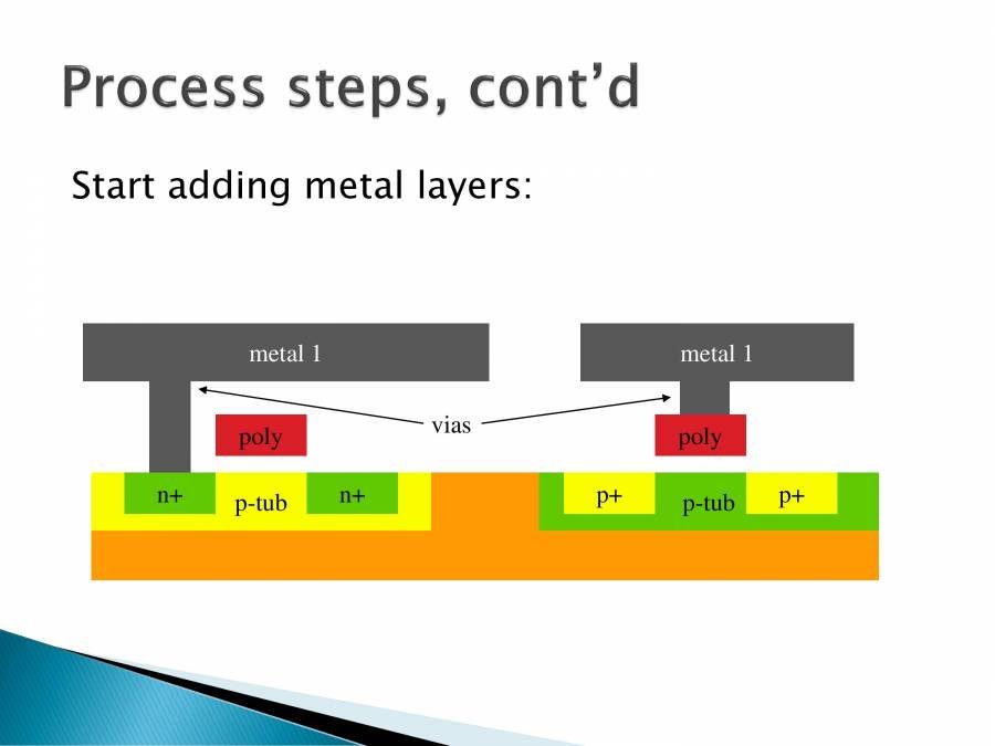
- Metallization: A metallic layer (e.g., aluminum, copper) is coated onto the wafer to form the interconnects that wire components together and protect them.
- Packaging: After electrical testing, individual ICs are separated from the wafer and sealed in protective packages (e.g., plastic or ceramic) to shield them from environmental factors and provide connections for the outside world.
Navigating the Nuances: Key Challenges & Best Practices
Understanding the distinct processes for IC boards and IC chips allows us to focus on the unique challenges and best practices for the board itself.
1. Signal Integrity: The Unseen Battle
High-speed ICs demand pristine signal quality. Managing signal integrity is a continuous battle.
- Impedance Control: Maintaining consistent impedance along traces, especially for high-frequency signals, prevents reflections and signal degradation. This requires careful trace width, dielectric material, and layer stack-up design.
- Crosstalk Mitigation: Signals on adjacent traces can interfere with each other (crosstalk). Proper spacing, differential pair routing, and strategic ground planes are essential to minimize this.
- Power Delivery Network (PDN) Design: Ensuring stable and clean power delivery to sensitive ICs is paramount. This involves carefully designing power planes, decoupling capacitors, and power trace widths to handle current demands and suppress noise.
2. Thermal Management: Keeping Your Cool
ICs generate heat, and excessive temperatures can lead to performance degradation or outright failure.
- Heat Dissipation: Design must account for heat pathways. This can involve using thermal vias to transfer heat to ground planes, incorporating heat sinks, or choosing PCB materials with better thermal conductivity.
- Component Placement: Spreading out high-power components or placing them near the edge of the board for better airflow helps.
- Simulation: Thermal simulations during the design phase are crucial to predict temperature hotspots and optimize cooling strategies.
3. Design for Manufacturability (DFM): The Proactive Approach
DFM isn't just a buzzword; it's a philosophy that integrates manufacturing considerations into the design process from day one.
- Early Collaboration: Designers should work closely with fabricators and assemblers from the schematic stage. Their insights can prevent costly redesigns later.
- Standardization: Using standard component footprints, trace widths, and via sizes can simplify manufacturing and reduce costs.
- Tolerances: Understanding and respecting manufacturing tolerances for drilling, etching, and component placement ensures reliable production. For instance, ensuring sufficient spacing between pads and traces (annular ring) for vias minimizes drilling mishaps.
- Fewer Layers, Lower Cost: While complex ICs need multi-layer boards, minimizing the layer count where possible can significantly reduce fabrication costs.
4. Cost Optimization: Balancing Performance and Budget
Every design decision has a cost implication.
- Material Choice: Specialty materials like Rogers are expensive; use them only when absolutely necessary.
- Component Selection: Off-the-shelf components are generally cheaper than custom or highly specialized parts.
- Test Strategy: While essential, extensive testing adds cost. Optimize test coverage to catch critical defects without over-testing.
- Yield Improvement: DFM best practices contribute directly to higher manufacturing yields, reducing scrap and rework costs.
5. Supply Chain & Sourcing: The Backbone of Production
Reliable sourcing of components and materials is fundamental.
- Qualified Suppliers: Partnering with reputable IC manufacturers, PCB fabricators, and assembly houses ensures quality and consistency.
- Lead Times: Understanding component lead times is critical for production planning and avoiding costly delays.
- Component Availability: Design choices should factor in the long-term availability of selected ICs and other components to avoid obsolescence issues.
Choosing the Right Partners: A Collaborative Endeavor
Producing a high-quality IC board is rarely a solo act. The success of your project hinges on effective collaboration between:
- IC Substrate Manufacturers: The specialists who produce the raw PCBs, often tailored to your specific material and layer requirements.
- Circuit Board Suppliers/Assemblers: Companies that handle component sourcing, SMT/THT assembly, and initial testing.
Their combined expertise ensures that your carefully designed blueprint is transformed into a robust, functional electronic marvel. Don't underestimate the value of open communication, early engagement, and mutual understanding of capabilities and limitations.
Your Next Step: From Concept to Reality
Manufacturing and fabrication considerations for IC boards are not an afterthought; they are an integral part of the design journey, influencing every decision from component selection to final assembly. By embracing a holistic approach that prioritizes DFM, understands material science, masters signal and thermal management, and fosters strong partnerships, you can navigate the complexities of IC board production with confidence. The result? High-performance, reliable, and cost-effective electronic devices that push the boundaries of innovation.